12
5
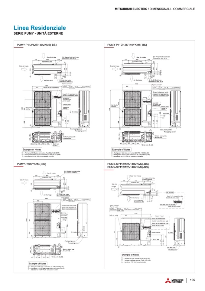
PUMY-P112/125/140VKM6(-BS
)
PUMY-P200YKM3(-BS
)
PUMY-P112/125/140YKM5(-BS)
PUMY-SP112/125/140VKM2(-BS)
PUMY-SP112/125/140YKM2(-BS)
MITSUBISHI ELECTRIC / DIMENSIONALI - COMMERCIAL
E
Linea Residenziale
SERIE PUMY - UNITÀ ESTERN
E
Unit : mm
• • •
Indication of STOP VALVE connection location
.
1
2
• • •
Refrigerant GAS pipe connection (FLARE) ø19.05 (3/4F
)
• • •
Refrigerant LIQUID pipe connection (FLARE) ø9.52 (3/8F
)
Example of Notes
*
1
PUMY-P200YKM3(-BS)
OUTDOOR UNIT
PUMY-P112/125/140VKM6(-BS
)
OUTDOOR UNIT
O
U
TDOOR UNI
T
PUMY-SP112/125/140VKM2(-BS
)
PUMY-SP112/125/140YKM2(-BS
)
OUTDOOR UNIT
PUMY SERIE
S
2-U Shaped notched hole
s
(Foundation Bolt M10
)
2-12×36 Oval hole
s
(Foundation Bolt M10
)
Side Air Intake
Rear Air Intake
Rear Air Intak
e
Air Discharg
e
70
60
42
225
3
3
0
4
0
2
8
600
225
Handle for
moving
Ground for the power supply
362
105
0
2
6
1
3
3
8
3
6
9
6
3
2
• • •
Indication of STOP VALVE connection location
.
1
2
• • •
Refrigerant GAS pipe connection (FLARE) ø15.88 (5/8F
)
• • •
Refrigerant LIQUID pipe connection (FLARE) ø9.52 (3/8F
)
Example of Notes
*1
• • •
Indication of STOP VALVE connection location
.
1
2
• • •
Refrigerant GAS pipe connection (FLARE) ø15.88 (5/8F
)
• • •
Refrigerant LIQUID pipe connection (FLARE) ø9.52 (3/8F
)
Example of Notes
*1
PUMY-P112/125/140YKM5(-BS
)
OUTDOOR UNIT
O
U
TDOOR UNI
T
225
600
225
2-U Shaped notched hole
s
(Foundation Bolt M10
)
Side Air Intak
e
4
0
3
3
0
Air Discharge
4
2
70
6
0
4
1
7
2
8
1
9
3
7
0
53
56
39
0
Installation Feet
2-12×36 Oval holes
(Foundation Bolt M10
)
From left to right
Terminal connectio
n
362
1050
Handle fo
r
moving
2
6
1
3
3
8
3
6
9
6
3
2
Service pane
l
Ground fo
r
the branch bo
x
power supply
Ground for the transmission line
Ground for concentration control
Handle fo
r
movin
g
Air Intak
e
Front piping cove
r
Rear piping cover
1
2
Ground for the power suppl
y
*
1
4
2
6
*
1
4
8
5
9
0
9
Bottom piping hole
(Knock-Out)
Drain hole (5-ø33)
8
6
81
45
160
160
160
110
1
5
4
1
3
6
From left to righ
t
For concentration
c
o
ntro
l
For the
transmission line
For the
branch bo
x
power supply
T
erminal connectio
n
For th
e
p
ower
suppl
y
Air Discharg
e
1050
362
2
6
1
3
3
8
3
6
9
6
3
2
Front piping cover
Rear piping cover
Ground for the transmission line
Ground for concentration contro
l
Ground for the power supply
Ground fo
r
the branch bo
x
power supply
Handle fo
r
movin
g
Service panel
3
9
3
4
5
0
9
8
6
Air Intak
e
Drain hole (5-ø33
)
Bottom piping hole
(Knock-Out)
8
6
1
5
4
1
3
6
81
45
160
160
160
110
2-U Shaped notched hole
s
(Foundation Bolt M10
)
Rear Air Intake
225
600
225
42
60
Side Air Intak
e
Installation Fee
t
4
0
3
3
0
1
9
2
8
3
7
0
4
1
7
53
56
39
0
2-12×36 Oval holes
(Foundation Bolt M10
)
Ground fo
r
the branch bo
x
power suppl
y
Installation Fee
t
53
56
39
0
4
1
7
1
9
3
7
0
From left to righ
t
Terminal connectio
n
Handle fo
r
moving
Ground for the transmission line
Ground for concentration control
Service panel
Air Intak
e
*
1
4
2
6
*
1
4
8
5
9
7
4
Front piping cover
Rear piping cove
r
1
2
Drain hol
e
(5-ø33
)
Bottom piping hol
e
(Knock-Out
)
8
6
81
45
160
160
16
0
110
1
5
4
1
3
6
Example of Note
s
A
R
E
A
R
E
A
R
E
A
R
E
Unit : mm
m
• • •
Indication of STOP VALVE connection location
.
1
2
• • •
Refrigerant GAS pipe connection (FLARE) ø19.05 (3/4F
)
• • •
Refrigerant LIQUID pipe connection (FLARE) ø9.52 (3/8F
)
Example of Note
s
*1
PUMY-P200YKM3(-BS
)
OUTDOOR UNIT
PUMY-P112/125/140VKM6(-BS)
OUTDOOR UNIT
O
U
TDOOR UNI
T
PUMY-SP112/125/140VKM2(-BS)
PUMY-SP112/125/140YKM2(-BS
)
OUTDOOR UNI
T
PUMY SERIE
S
2-U Shaped notched holes
(Foundation Bolt M10
)
2-12×36 Oval hole
s
(Foundation Bolt M10
)
Side Air Intake
Rear Air Intake
Rear Air Intake
Air Discharg
e
70
60
42
225
3
3
0
4
0
2
8
600
225
Handle for
moving
Ground for the power supply
362
105
0
2
6
1
3
3
8
3
6
9
6
3
2
• • •
Indication of STOP VALVE connection location
.
1
2
• • •
Refrigerant GAS pipe connection (FLARE) ø15.88 (5/8F
)
• • •
Refrigerant LIQUID pipe connection (FLARE) ø9.52 (3/8F
)
Example of Notes
*1
• • •
Indication of STOP VALVE connection location
.
1
2
• • •
Refrigerant GAS pipe connection (FLARE) ø15.88 (5/8F
)
• • •
Refrigerant LIQUID pipe connection (FLARE) ø9.52 (3/8F
)
Example of Note
s
*1
PUMY-P112/125/140YKM5(-BS)
OUTDOOR UNIT
O
U
TDOOR UNI
T
225
600
225
2-U Shaped notched hole
s
(Foundation Bolt M10
)
Side Air Intak
e
4
0
3
3
0
Air Discharg
e
42
70
60
4
1
7
2
8
1
9
3
7
0
53
56
39
0
Installation Feet
2-12×36 Oval hole
s
(Foundation Bolt M10
)
From left to righ
t
Terminal connection
362
1050
Handle for
moving
2
6
1
3
3
8
3
6
9
6
3
2
Service panel
Ground for
the branch box
power supply
Ground for the transmission lin
e
Ground for concentration contro
l
Handle fo
r
movin
g
Air Intake
Front piping cove
r
Rear piping cover
1
2
Ground for the power suppl
y
*
1
4
2
6
*
1
4
8
5
9
0
9
Bottom piping hole
(Knock-Out)
Drain hole (5-ø33)
8
6
81
45
160
160
160
110
1
5
4
1
3
6
From left to righ
t
For concentration
c
o
ntro
l
For the
transmission lin
e
For the
branch box
power supply
T
erminal connectio
n
For th
e
p
ower
suppl
y
Air Discharge
105
0
362
2
6
1
3
3
8
3
6
9
6
3
2
Front piping cover
Rear piping cover
Ground for the transmission line
Ground for concentration contro
l
Ground for the power suppl
y
Ground for
the branch box
power supply
Handle for
moving
Service panel
3
9
3
4
5
0
9
8
6
Air Intak
e
Drain hole (5-ø33)
Bottom piping hole
(Knock-Out
)
8
6
1
5
4
1
3
6
81
45
160
160
160
110
2-U Shaped notched holes
(Foundation Bolt M10
)
Rear Air Intak
e
225
600
225
42
60
Side Air Intak
e
Installation Feet
4
0
3
3
0
1
9
2
8
3
7
0
4
1
7
53
56
39
0
2-12×36 Oval hole
s
(Foundation Bolt M10
)
Ground for
the branch box
power supply
Installation Feet
53
56
39
0
4
1
7
1
9
3
7
0
From left to righ
t
Terminal connectio
n
Handle
for
moving
Ground for the transmission line
Ground for concentration control
Service panel
Air Intak
e
*
1
4
2
6
*
1
4
8
5
9
7
4
Front piping cove
r
Rear piping cove
r
1
2
Drain hole
(5-ø33
)
Bottom piping hole
(Knock-Out)
8
6
81
45
160
160
16
0
110
1
5
4
1
3
6
Example of Note
s
F
LARE
F
LARE
F
LARE
F
LARE
Unit : mm
m
• • •
Indication of STOP VALVE connection location
.
1
2
• • •
Refrigerant GAS pipe connection (FLARE) ø19.05 (3/4F
)
• • •
Refrigerant LIQUID pipe connection (FLARE) ø9.52 (3/8F
)
Example of Note
s
*
1
PUMY-P200YKM3(-BS)
OUTDOOR UNIT
PUMY-P112/125/140VKM6(-BS
)
OUTDOOR UNIT
O
U
TDOOR UNIT
PUMY-SP112/125/140VKM2(-BS)
PUMY-SP112/125/140YKM2(-BS)
OUTDOOR UNIT
PUMY SERIES
2-U
Shaped notched holes
(Foundation Bolt M10)
2-12×36 Oval holes
(Foundation Bolt M10)
Side Air Intak
e
Rear Air Intak
e
Rear Air Intak
e
Air Discharge
70
60
42
225
3
3
0
4
0
2
8
600
225
Handle for
moving
Ground for the power suppl
y
362
105
0
2
6
1
3
3
8
3
6
9
6
3
2
• • •
Indication of STOP VALVE connection location
.
1
2
• • •
Refrigerant GAS pipe connection (FLARE) ø15.88 (5/8F
)
• • •
Refrigerant LIQUID pipe connection (FLARE) ø9.52 (3/8F
)
Example of Note
s
*1
• • •
Indication of STOP VALVE connection location
.
1
2
• • •
Refrigerant GAS pipe connection (FLARE) ø15.88 (5/8F
)
• • •
Refrigerant LIQUID pipe connection (FLARE) ø9.52 (3/8F
)
Example of Notes
*
1
PUMY-P112/125/140YKM5(-BS)
OUTDOOR UNIT
O
U
TDOOR UNI
T
225
600
22
5
2-U Shaped notched holes
(Foundation Bolt M10)
Side Air Intak
e
4
0
3
3
0
Air Discharg
e
42
70
6
0
4
1
7
2
8
1
9
3
7
0
53
56
3
9
0
Installation Feet
2-12×36 Oval holes
(Foundation Bolt M10)
From left to righ
t
Terminal connection
362
105
0
Handle
for
movin
g
2
6
1
3
3
8
3
6
9
6
3
2
Service panel
Ground for
the branch bo
x
power suppl
y
Ground for the transmission line
Ground for concentration control
Handle fo
r
moving
Air Intake
Front piping cove
r
Rear piping cover
1
2
Ground for
the power supply
*
1
4
2
6
*
1
4
8
5
9
0
9
Bottom
piping hole
(Knock-Out
)
Drain hole (5-ø33)
8
6
81
45
16
0
160
16
0
110
1
5
4
1
3
6
From left to right
For concentration
c
o
ntro
l
For the
transmission lin
e
For the
branch bo
x
power suppl
y
T
erminal connectio
n
For th
e
p
ower
suppl
y
Air Discharge
105
0
362
2
6
1
3
3
8
3
6
9
6
3
2
Front piping cover
Rear piping cover
Ground for the transmission line
Ground for concentration contro
l
Ground for the power suppl
y
Ground for
the branch box
power supply
Handle for
movin
g
Service pane
l
3
9
3
4
5
0
9
8
6
Air Intake
Drain hole (5-ø33
)
Bottom piping hol
e
(Knock-Out
)
8
6
1
5
4
1
3
6
8
1
45
160
160
16
0
11
0
2-U Shaped notched holes
(Foundation Bolt M10
)
Rear Air Intake
225
600
225
42
6
0
Side Air Intake
Installation Feet
4
0
3
3
0
1
9
2
8
3
7
0
4
1
7
5
3
5
6
39
0
2-12×36 Oval holes
(Foundation Bolt M10)
Ground for
the branch box
power supply
Installation Fee
t
53
56
3
9
0
4
1
7
1
9
3
7
0
From left to righ
t
Terminal connection
Handle fo
r
moving
Ground for the transmission line
Ground for concentration control
Service panel
Air Intake
*
1
4
2
6
*
1
4
8
5
9
7
4
Front piping cove
r
Rear piping cove
r
1
2
Drain hol
e
(5-ø33
)
Bottom piping hole
(Knock-Out
)
8
6
8
1
45
160
160
16
0
110
1
5
4
1
3
6
Example of Note
s
LIQ 6.35(1/4")FLARE
GAS 12.7(1/2")FLAR
E
LIQ 6.35(1/4")FLARE
GAS 9.52(3/8")FLAR
E
Unit : mm
Unit : m
m
• • •
Indication of STOP VALVE connection location
.
1
2
• • •
Refrigerant GAS pipe connection (FLARE) ø19.05 (3/4F
)
• • •
Refrigerant
LIQUID pipe connection (FLARE) ø9.52 (3/8F)
Example of Note
s
*
1
PUMY-P200YKM3(-BS
)
OUTDOOR UNI
T
PUMY-P112/125/140VKM6(-BS
)
OUTDOOR UNIT
O
U
TDOOR UNI
T
PUMY-SP112/125/140VKM2(-BS)
PUMY-SP112/125/140YKM2(-BS)
OUTDOOR UNIT
PUMY SERIES
2-U Shaped notched holes
(Foundation Bolt M10
)
2-12×36 Oval holes
(Foundation Bolt M10)
Side Air Intak
e
Rear Air Intak
e
Rear Air Intak
e
Air Discharge
70
60
4
2
22
5
3
3
0
4
0
2
8
600
225
Handle for
moving
Ground for the power suppl
y
362
105
0
2
6
1
3
3
8
3
6
9
6
3
2
• • •
Indication of STOP VALVE connection location
.
1
2
• • •
Refrigerant GAS pipe connection (FLARE) ø15.88 (5/8F
)
• • •
Refrigerant LIQUID pipe connection (FLARE) ø9.52 (3/8F
)
Example of Note
s
*1
• • •
Indication of STOP VALVE connection location
.
1
2
• • •
Refrigerant GAS pipe connection (FLARE) ø15.88 (5/8F
)
• • •
Refrigerant LIQUID pipe connection (FLARE) ø9.52 (3/8F
)
Example of Notes
*
1
PUMY-P112/125/140YKM5(-BS)
OUTDOOR UNIT
O
U
TDOOR UNI
T
225
600
22
5
2-U Shaped notched holes
(Foundation Bolt M10
)
Side Air Intak
e
4
0
3
3
0
Air Discharg
e
42
70
6
0
4
1
7
2
8
1
9
3
7
0
5
3
5
6
3
9
0
Installation Feet
2-12×36 Oval holes
(Foundation Bolt M10
)
From left to right
Terminal connection
362
105
0
Handle
for
movin
g
2
6
1
3
3
8
3
6
9
6
3
2
Service pane
l
Ground for
the branch bo
x
power suppl
y
Ground for the transmission lin
e
Ground for concentration contro
l
Handle fo
r
moving
Air Intake
Front piping cove
r
Rear piping cover
1
2
Ground for the power suppl
y
*
1
4
2
6
*
1
4
8
5
9
0
9
Bottom piping hol
e
(Knock-Out
)
Drain hole (5-ø33)
8
6
81
45
16
0
160
16
0
110
1
5
4
1
3
6
From left to right
For concentration
c
o
ntro
l
For the
transmission lin
e
For the
branch bo
x
power suppl
y
T
erminal connectio
n
For th
e
p
ower
supply
Air Discharge
105
0
36
2
2
6
1
3
3
8
3
6
9
6
3
2
Front piping cover
Rear piping cove
r
Ground for the transmission line
Ground for concentration control
Ground for the power suppl
y
Ground for
the branch box
power supply
Handle for
movin
g
Service pane
l
3
9
3
4
5
0
9
8
6
Air Intake
Drain hole (5-ø33
)
Bottom piping hol
e
(Knock-Out
)
8
6
1
5
4
1
3
6
8
1
45
160
160
160
110
2-U Shaped notched holes
(Foundation Bolt M10
)
Rear Air Intak
e
225
600
22
5
42
60
Side Air Intak
e
Installation Fee
t
4
0
3
3
0
1
9
2
8
3
7
0
4
1
7
5
3
5
6
39
0
2-12×36 Oval holes
(Foundation Bolt M10
)
Ground for
the branch box
power supply
Installation Fee
t
53
56
3
9
0
4
1
7
1
9
3
7
0
From left to right
Terminal connection
Handle fo
r
moving
Ground for the transmission line
Ground for concentration control
Service panel
Air Intake
*
1
4
2
6
*
1
4
8
5
9
7
4
Front piping cove
r
Rear piping cove
r
1
2
Drain hol
e
(5-ø33
)
Bottom piping hole
(Knock-Out
)
8
6
8
1
45
160
160
160
110
1
5
4
1
3
6
Example of Notes

